Data can be represented in various ways, as defined by the Type option:
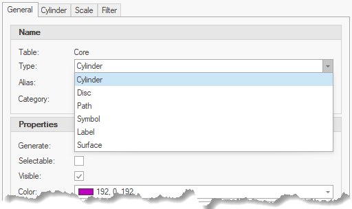
Changing the Type property changes the tabs shown:
Cylinder
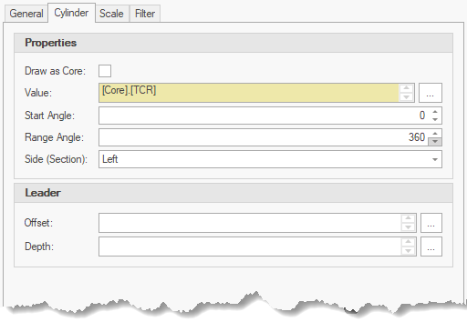
Properties
•Draw As Core - used to display the generated objects as a core cylinder (disables all other properties).
•Value - defines the radius value in drawing units.
•Start Angle - indicates the angle to start drawing the cylinder (used for segments).
•Range Angle - defines the angle (in degrees) for segments - typically 360 for complete cylinders.
•Side (Section) - defines which side to the core that cylinders are displayed on sections.
Leader
•Offset - indicates the horizontal offset of the leader.
•Depth - indicates the actual depth of the leader end (i.e. water level).
Disc
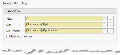
Properties
•Relative to hole axis - draws the disc relative to the hole axis (i.e. alpha and beta angles).
•Value - defines the radius value in drawing units.
•Dip - defines the angle of surface dip, measured from horizontal positive down in degrees.
•Direction - defines angle of the dip direction, measured clockwise from north in degrees.
Path
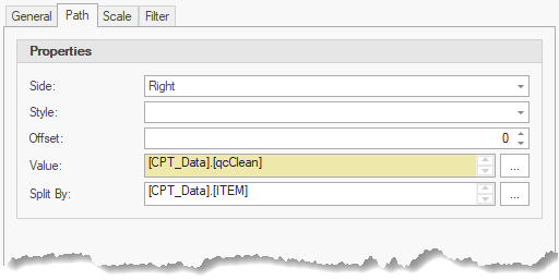
Properties
•Side - indicates the side of the core that the line plot is shown.
•Offset - indicates the offset of the line plot from the core axis (i.e. enables horizontal stacking).
•Value - defines the offset value in drawing units.
•Split By - splits data from a single investigation location into multiple line plots (i.e. multiple CPT sounding / DCP data).
Symbol
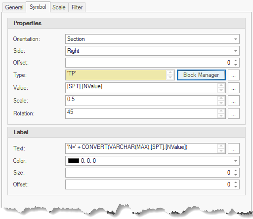
Properties
•Orientation - indicates if the symbol is shown in the plan or section orientation.
•Side (section orientation only) - indicates the side of the core that the symbol is shown.
•Offset - indicates the offset of the symbol from the core axis.
•Type - indicates the expression or constant name of the symbol (see block definition names).
•Value - defines the offset value in drawing units.
•Scale - defines the scaling of symbols (default = 1).
•Rotation - defines the rotation of symbols (default = 0).
Labels
•Text - defines text associated with a label.
•Color - defines the text color.
•Size - defines the text size in drawing units.
•Offset - defines the offset from the symbol in drawing units.
Label
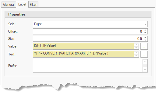
Properties
•Side - indicates the side of the core that the label is shown.
•Offset - indicates the offset of the label from the core axis.
•Size - defines the text size in drawing units.
•Value - defines the offset value in drawing units.
•Text - defines text associated with a label.
•Prefix - defines a constant string shown before the text.
Surface
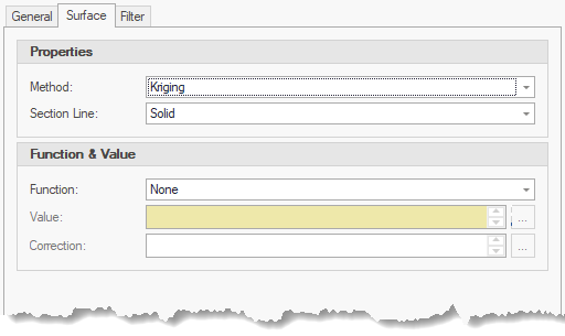
Properties
•Method - defines the method used to generate the surface (i.e. Kriging).
•Section Line - defines the line type presented on sections.
Function & Value
•Function - defines the data function used to present data.
•Value - defines the vertical offset value in drawing units.
•Correction - used to correct values (i.e. CPT soundings with variable reading intervals).
|
Value and Correction are disabled when Function is set to 'None' |
