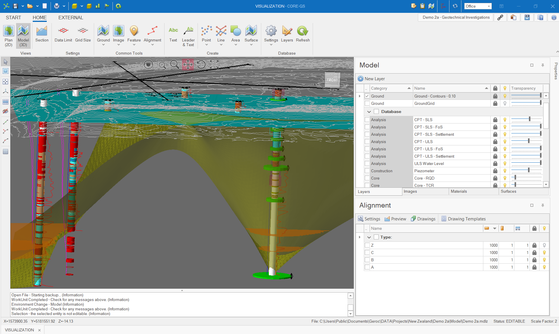
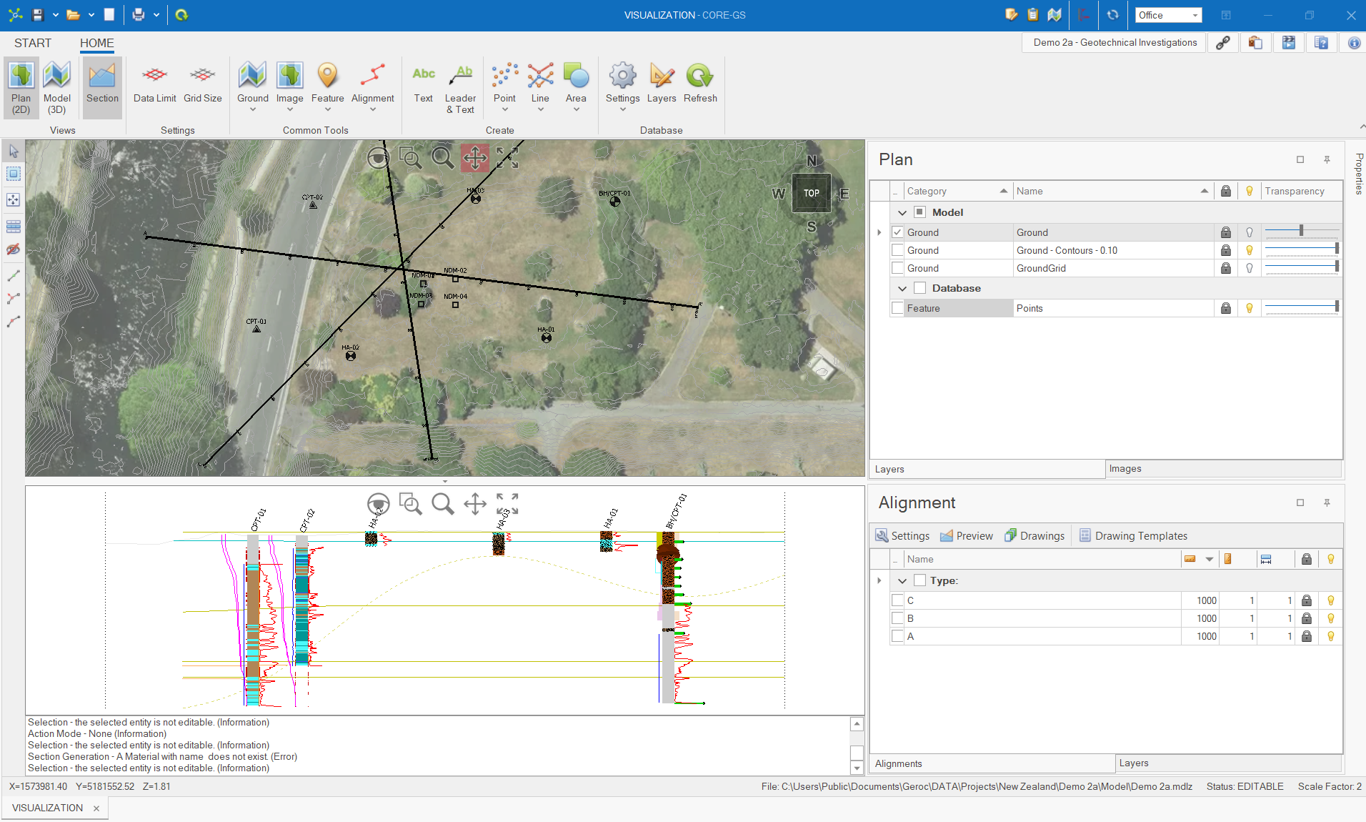
The Visualisation Module is made up of two interfaces; Models and Drawings:
Models
A model is a collection of entities that represent data in 2D/3D space and can contain data from the database and from various external sources (i.e. images and CAD data).
All entities are persisted to a model file (*.mdlz) that is self-contained. This allows multiple models to be associated to a single project allowing different versions of the model to be maintained, or models of smaller areas to be created.
The model is viewed through the model viewport that can be switch between a 2D and 3D environment providing different capabilities.
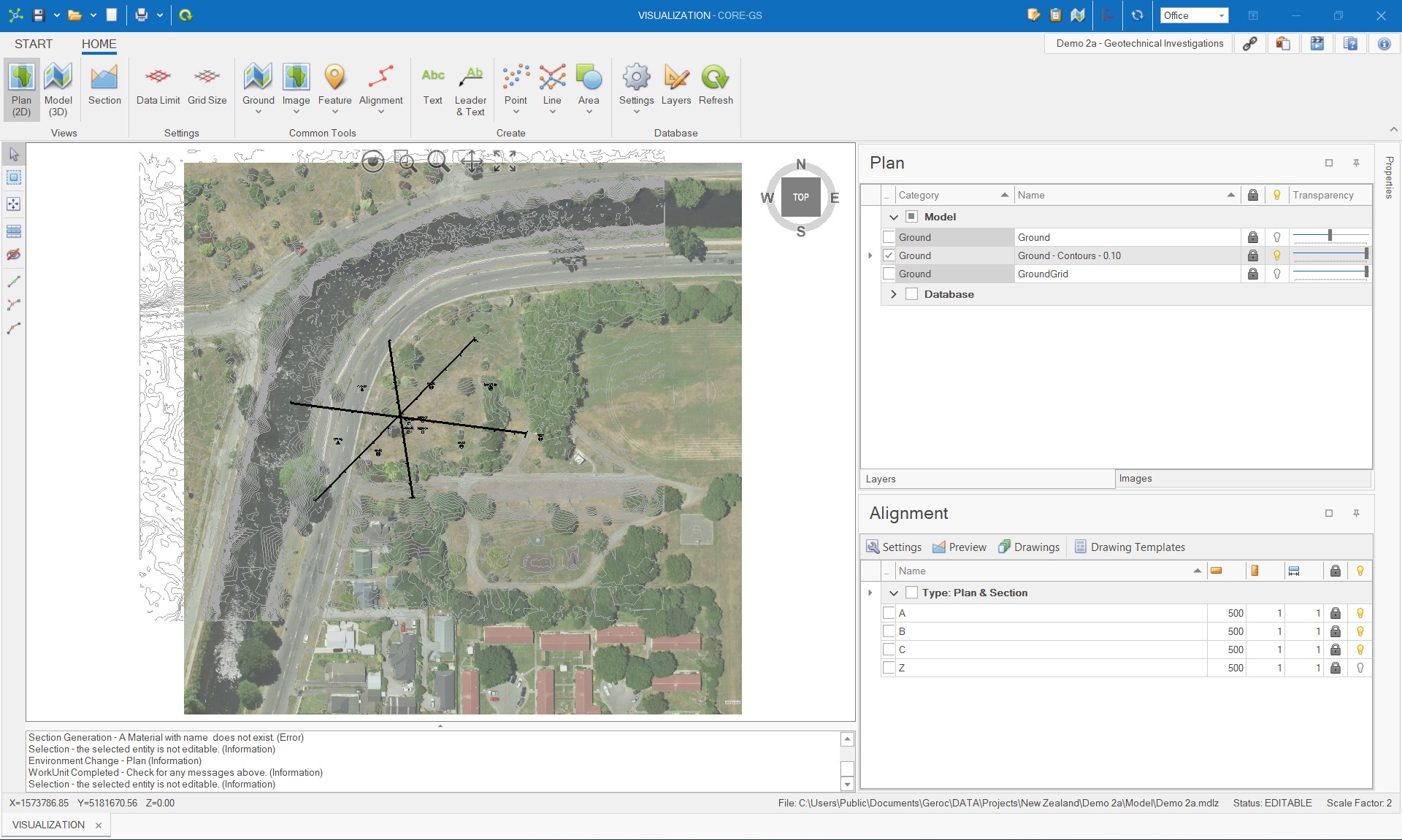
In the 2D environment the user is provided with a simplified interface to view georeferenced images, create ground surfaces from external files, use the pin to ground tool to assign elevations from the ground surface to database point features and define alignments for sections and drawings. In this environment only a limited number of predefined layers are visible:
The 3D environment provides a fully functional, interactive interface to visually assess and interpret data patterns, assign materials, generate surfaces and define surface limits (requires CORE-GS | Professional). Additionally model data (i.e. CAD) can be import and export through this environment:
An alignment (mentioned above) is a special type of linear object created in a model that defines the geometry of sections and drawings.
Before an alignment can be used to generate a section and/or drawing, it needs be associated to a drawing template to determine the type of drawing (i.e. Plan, Section or Plan & Section) that will be generated from a alignment.
Alignments can be defined either as a single or multiple segment line.
Single segment alignments are defined by two points; a start and end. These are typically used on smaller sites (i.e. residential property) and 2D slope stability assessments:
Multiple segment alignments are defined by more than two points. These are typically used on corridor type projects (i.e. pipelines, roads, tunnels):
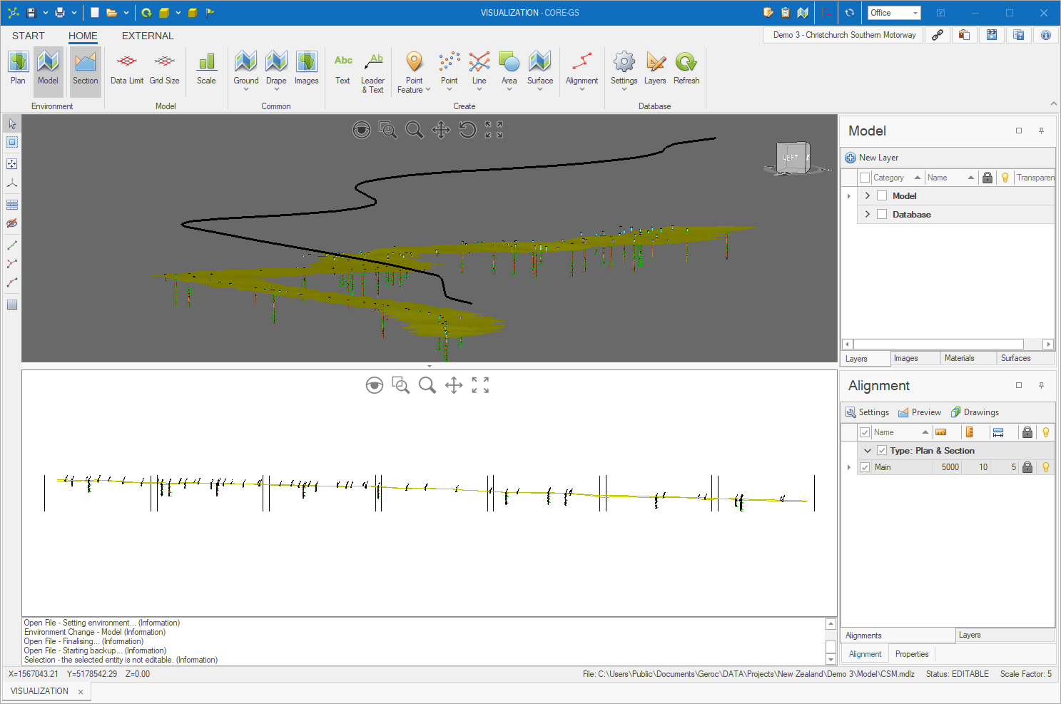
When an alignment is previewed, a section will be generated if it is defined in the associated drawing template.
A section is a special 2D model that is built from the model.
Data from selected point features (i.e. boreholes) are projected onto the nearest line segment while surfaces are intersected directly below the alignment.
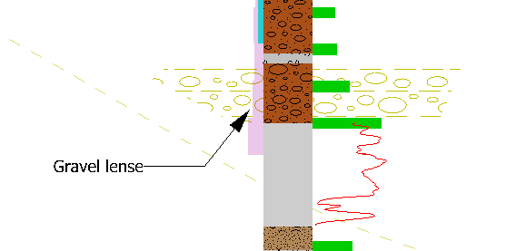
Annotations can be added to any viewport (i.e. plan, model or section) to provide user interpretations.
These may include text, text with leaders, points, lines and areas (with CAD hatch support).
Drawings
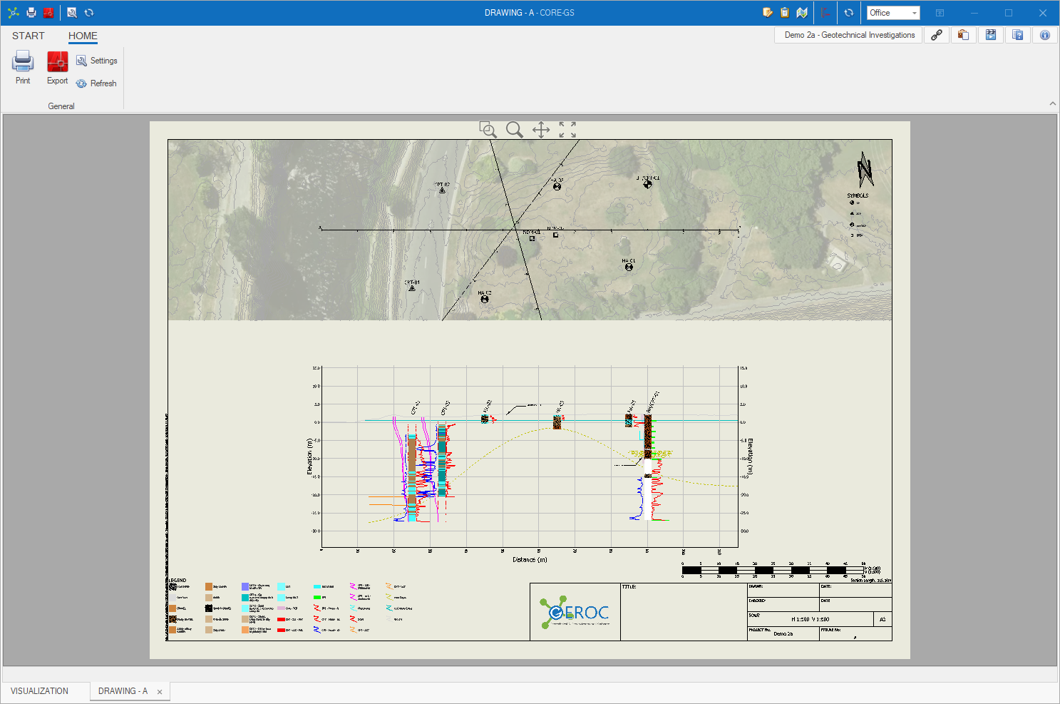
A drawing is a scaled graphical output from a model and/or section and are typically generated once annotations have been completed.
Each alignment is associated to a drawing template that defines the type and layout of the drawing when this is generated.
In the following sections we'll cover the development of models, definition of alignments and generation of drawings.
Firstly we'll cover the basic steps of model setup:
•Setting the data limit & grid size
•Getting data from the database
•Editing features (create, move and assign elevations)
Next we'll cover the definition of alignments and generation of sections:
These will be followed by looking at advanced modelling tools (CORE-GS | Professional only):
